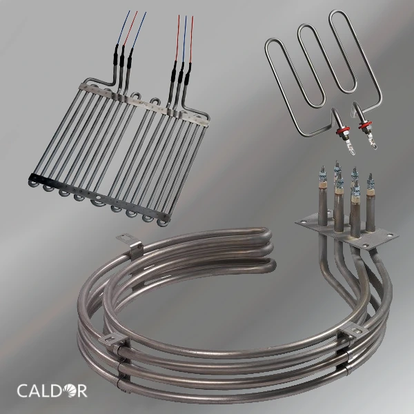
Caldor proiectează și produce rezistențe electrice tubulare în orice formă necesară.
Caldor proiectează și produce rezistențe electrice tubulare îndoite pentru a se potrivi chiar și celor mai complexe geometrii și constrângeri de instalare. Folosind tehnici avansate de formare și inginerie adaptată aplicației, asigurăm distribuție precisă a căldurii, integritate mecanică și fiabilitate pe termen lung în medii industriale solicitante.
Pentru forme speciale, suport tehnic și soluții dedicate proiectului, contactați echipa noastră de inginerie pentru a discuta cerințele aplicației dumneavoastră.
Request a quote!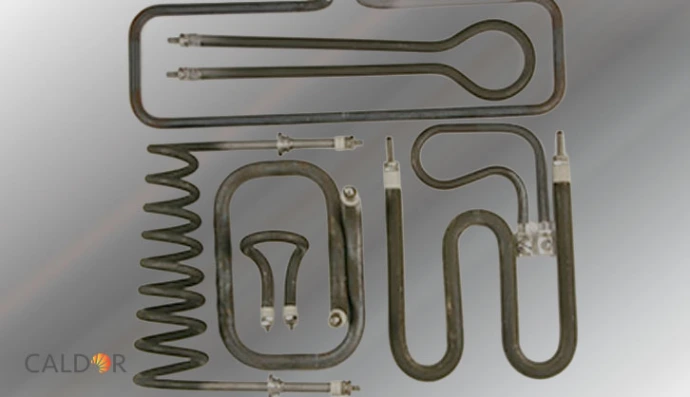
Rezistențe electrice tubulare îndoite în orice formă necesară.
Proiectate pentru geometrii complexe și performanță termică precisă.
Caldor proiectează și produce rezistențe electrice tubulare formate pentru a se potrivi chiar și celor mai complexe forme și constrângeri de instalare. Prin tehnici avansate de îndoire și inginerie adaptată aplicației, asigurăm distribuție uniformă a căldurii, stabilitate mecanică și durată lungă de funcționare în medii industriale solicitante.
Indiferent dacă aplicația dumneavoastră implică lichide, gaze sau materiale solide, rezistențele noastre electrice tubulare proiectate la comandă se integrează perfect în designul sistemului dumneavoastră. Pentru consultanță tehnică, geometrii personalizate și soluții dedicate proiectului, contactați echipa noastră de inginerie pentru a discuta cerințele aplicației dumneavoastră..
Caracteristici principale
- Îndoire personalizată în orice formă: Rezistențele electrice tubulare pot fi formate cu precizie pentru a se potrivi geometriilor simple sau foarte complexe și diferitelor constrângeri de instalare..
- Distribuție uniformă și eficientă a căldurii: Designul optimizat al spiralei interne și izolația compactată cu MgO asigură performanță termică constantă pe întreaga lungime încălzită.
- Gamă largă de aplicații: Potrivite pentru încălzirea lichidelor, gazelor și materialelor solide în rezervoare, conducte, sisteme de încălzire a aerului, matrițe și echipamente de proces.
- Materiale de teacă de înaltă calitate: Disponibile în oțeluri inoxidabile, aliaje Incoloy®, titan, cupru și oțel carbon pentru a se potrivi cerințelor de temperatură, coroziune și mediu de lucru.
- Tehnologie avansată de izolație MgO: Oxidul de magneziu de înaltă puritate, compactat, oferă rezistență dielectrică excelentă și transfer eficient al căldurii.
- Configurații flexibile de putere și tensiune: Putere (wattaj), tensiune și distribuție a puterii realizate la comandă, în funcție de aplicație și condițiile de operare.
- Opțiuni robuste de etanșare și conexiune: Mai multe sisteme de etanșare și configurații de terminal disponibile pentru medii dure sau temperaturi ridicate.
- Soluții ATEX disponibile: Rezistențe electrice tubulare conforme ATEX pot fi furnizate pentru aplicații în zone periculoase, în funcție de specificațiile proiectului.
- Inginerie și producție europeană: Proiectate și fabricate în România, asigurând calitate constantă, timpi rapizi de răspuns și suport tehnic direct din partea inginerilor.
Media Compatibility & Technical Characteristics
Which media can tubular heating elements be used for?
Caldor tubular heating elements are designed for reliable operation in a wide range of liquids, gases, and solid materials. Proper selection of watt density, sheath material, and tube diameter is essential to ensure long service life, corrosion resistance, and thermal stability.
Water applications – recommended loads and materials
- Stagnant water: 8–12 W/cm² · Copper, AISI 321, AISI 316L
- Circulating water: 10–16 W/cm² · Copper, AISI 316L, Incoloy® 800 / 825
- Boric water: up to 8 W/cm² · AISI 316L
- Boiler water: 8–16 W/cm² · AISI 316L, Incoloy® 800 / 825
- Chlorinated water: up to 6 W/cm² · Incoloy® 825
- Sea water: 3.5–6 W/cm² · Incoloy® 825, Inconel® 600
- Demineralized / deionized / distilled water: 4–6 W/cm² · AISI 316L, Incoloy® 800 / 825
- Domestic hot water: 4–8 W/cm² · Copper, AISI 316L, Incoloy® 825
- Caustic water (2%–70%): 2.3–7 W/cm² · AISI 316L, Incoloy® 825, Inconel® 600
Oil heating applications
- Fuel oil pre-heating / light fuel oil: 1–2 W/cm² · AISI 321, AISI 316L
- Heavy fuel oil: 0.5–3.5 W/cm² (depending on grade) · AISI 316L
- Gasoline / kerosene: 3.0–3.5 W/cm² · AISI 316L
- Machine oils (SAE 10–50): 2.0–3.5 W/cm² · AISI 316L
- Mineral oils: 0.5–3.5 W/cm² · AISI 321, AISI 316L
- Lubricating oils: up to 2.3 W/cm² · AISI 321, AISI 316L
Acids and corrosive fluids
- Acetic acid: up to 6 W/cm² · AISI 316L, Incoloy® 825
- Boric acid: up to 6 W/cm² · Incoloy® 825
- Chloric, hydrofluoric, nitric, sulphuric acids: up to 1.5 W/cm² · PTFE-coated sheath
- Alkaline baths: up to 6 W/cm² · AISI 321 (non-corrosive), AISI 316L
- Phosphate baths: up to 4 W/cm² · AISI 316L, Incoloy® 825
Glycol-based fluids
- Ethylene / propylene glycol: 4–8 W/cm² (depending on concentration) · AISI 321, AISI 316L
Gas heating applications
- Air (static or circulating): 0.1–8 W/cm² · AISI 321 / AISI 309
- Natural gas: 0.1–8 W/cm² · AISI 321, AISI 316L
- Argon / nitrogen: Load depends on sheath temperature · AISI 321, 316L, Incoloy® 825, Inconel® 600
- Propane / butane: Load depends on sheath temperature · AISI 321, AISI 316L
- Oxygen / hydrogen: Load depends on sheath temperature · AISI 316L
Solid materials and cast-in applications
- Aluminium, brass, bronze (cast-in): 4–15 W/cm² · AISI 309
- Copper-nickel cast-in: 5–10 W/cm² · AISI 309
- Oxychlorination: up to 3 W/cm² · Incoloy® 800 / 825
- Calcination processes: up to 3 W/cm² · Incoloy® 800 / 825
- Hydrocarbon regeneration: up to 2 W/cm² · Incoloy® 800 / 825
How are tubular heating elements technically designed?
Watt density, tube diameter, and sheath material are selected to optimize reliability, corrosion resistance, and temperature performance.
- Tube diameters: 6.5 / 8.5 / 10 / 13.5 / 16 mm
- Sheath materials: AISI 321, AISI 316L, AISI 309, Incoloy® 800 / 825, Inconel® 600, Titanium
- Optional coatings: PTFE (Teflon™), Halar
- Tube types: Sealed tube (standard), seamless tube (on request)
Electrical characteristics and tolerances
- Maximum voltage: Ø6.5 → 400 V · Ø8.5 → 415 V · Ø10 → 500 V · Ø13.5 → 690 V · Ø16 → 750 V
- Resistance tolerance: −5% / +10%
- Power tolerance: <100 W: ±10% · >100 W: +5% / −10%
Mechanical construction and tolerances
- Sheaths: Rolled, welded, or seamless tubes manufactured to ASTM / DIN standards
- Forming: Straight or custom-bent geometries according to specifications
- Diameter tolerance: ±0.1 mm
- Length tolerance: ±1% (minimum +5 mm)
Why proper media selection is critical?
Selecting the correct watt density and sheath material according to the heated medium is essential to prevent overheating, corrosion, and premature failure. Caldor engineering support ensures each tubular heating element is optimized for safe, reliable, and long-term operation.
Tubular Heating Elements – Technical FAQ
Media & Applications
Caldor tubular heating elements are designed for heating liquids, gases, and solid materials. They are used in process equipment where reliable heat transfer is required, including tanks, vessels, pipelines, air heating systems, tooling, and custom industrial machinery.
Technical Description
Tubular heating elements consist of a metallic sheath with a resistive coil embedded in MgO insulation. This construction provides efficient thermal conductivity, dielectric strength, and long-term mechanical stability.
Heating Element (Active Zone)
- Engineered coil layout for uniform or application-specific heat distribution
- Optimized watt density selection based on the heated medium and heat dissipation
- Consistent thermal output for continuous-duty industrial operation
Non-Heating Part (Cold Zone)
- Cold ends can be designed as short, medium, or long according to installation constraints
- Supports safer terminal temperatures and improved connection durability
- Helps protect seals and terminals in high-temperature zones
Material Characteristics
Sheath material selection is defined by the working medium, corrosion risk, and admissible temperatures. Typical options include stainless steels and high-temperature / corrosion-resistant alloys, as well as special materials for aggressive environments.
- Stainless steels: balanced performance for general industrial environments
- High-temperature alloys: improved oxidation and residue resistance at elevated temperatures
- Corrosion-focused materials: optimized for chemical media and demanding applications
Electrical Features
- Voltage and wattage tailored to the application
- Stable dielectric strength enabled by MgO insulation
- Power tolerance and electrical safety checks defined by the selected class and project requirements
Mechanical Features
- Robust sheath for mechanical durability in industrial environments
- Design support for vibration, thermal cycling, and continuous-duty operation
- Custom lengths, diameters, and mounting interfaces available
Connecting Terminals
- Multiple terminal types available (threaded studs, fast-on tabs, lead wires, ceramic heads)
- Connection materials and insulation selected according to temperature and environment
- Custom terminal configurations available for OEM integration
Bending & Forming (Custom Shapes)
Caldor can bend tubular heating elements to match required geometries, including complex shapes. Bending is engineered to preserve electrical integrity, heat distribution, and mechanical strength.
- U-shapes, hairpins, coils, multi-bends, and custom contours
- Geometry defined according to installation space and heat transfer requirements
- Design support available based on drawings or application sketches
Assembly Parts
- Mounting and fixing accessories (depending on application)
- Sealing systems to reduce moisture and contaminant ingress
- Protection components for terminals and connection areas
Certification (If Requested)
Certification and documentation can be prepared according to project scope. For hazardous environments, ATEX-related configurations may be offered depending on the application requirements.
Manufacturing Tests
- Electrical safety testing (dielectric strength and insulation checks)
- Dimensional verification according to project tolerances
- Power and resistance validation based on design specifications
For custom products, test parameters are defined during engineering to match the application and required compliance.
Options
- Various dimensions (Ø / length) and custom geometries
- Voltage and wattage variations
- Cold zones and application-specific power distribution
- Multiple terminal and lead configurations
- Material and sealing selection according to the working medium
References
Caldor tubular heating elements are supplied to industrial customers where reliability and quality are essential. As a critical “engine” of the final equipment or process, our heaters are engineered for dependable operation and long service life.
Tubular Heating Elements
Media & Applications
Caldor tubular heating elements are designed for heating liquids, gases, and solid materials. They are used in process equipment where reliable heat transfer is required, including tanks, vessels, pipelines, air heating systems, tooling, and custom industrial machinery.
Technical Description
Tubular heating elements consist of a metallic sheath with a resistive coil embedded in MgO insulation. This construction provides efficient thermal conductivity, dielectric strength, and long-term mechanical stability.
Heating Element (Active Zone)
- Engineered coil layout for uniform or application-specific heat distribution
- Optimized watt density selection based on the heated medium and heat dissipation
- Consistent thermal output for continuous-duty industrial operation
Non-Heating Part (Cold Zone)
- Cold ends can be designed as short, medium, or long according to installation constraints
- Supports safer terminal temperatures and improved connection durability
- Helps protect seals and terminals in high-temperature zones
Material Characteristics
Sheath material selection is defined by the working medium, corrosion risk, and admissible temperatures. Typical options include stainless steels and high-temperature / corrosion-resistant alloys, as well as special materials for aggressive environments.
- Stainless steels: balanced performance for general industrial environments
- High-temperature alloys: improved oxidation and residue resistance at elevated temperatures
- Corrosion-focused materials: optimized for chemical media and demanding applications
Electrical Features
- Voltage and wattage tailored to the application
- Stable dielectric strength enabled by MgO insulation
- Power tolerance and electrical safety checks defined by the selected class and project requirements
Mechanical Features
- Robust sheath for mechanical durability in industrial environments
- Design support for vibration, thermal cycling, and continuous-duty operation
- Custom lengths, diameters, and mounting interfaces available
Connecting Terminals
- Multiple terminal types available (threaded studs, fast-on tabs, lead wires, ceramic heads)
- Connection materials and insulation selected according to temperature and environment
- Custom terminal configurations available for OEM integration
Bending & Forming (Custom Shapes)
Caldor can bend tubular heating elements to match required geometries, including complex shapes. Bending is engineered to preserve electrical integrity, heat distribution, and mechanical strength.
- U-shapes, hairpins, coils, multi-bends, and custom contours
- Geometry defined according to installation space and heat transfer requirements
- Design support available based on drawings or application sketches
Assembly Parts
- Mounting and fixing accessories (depending on application)
- Sealing systems to reduce moisture and contaminant ingress
- Protection components for terminals and connection areas
Certification (If Requested)
Certification and documentation can be prepared according to project scope. For hazardous environments, ATEX-related configurations may be offered depending on the application requirements.
Manufacturing Tests
- Electrical safety testing (dielectric strength and insulation checks)
- Dimensional verification according to project tolerances
- Power and resistance validation based on design specifications
For custom products, test parameters are defined during engineering to match the application and required compliance.
Options
- Various dimensions (Ø / length) and custom geometries
- Voltage and wattage variations
- Cold zones and application-specific power distribution
- Multiple terminal and lead configurations
- Material and sealing selection according to the working medium
References
Caldor tubular heating elements are supplied to industrial customers where reliability and quality are essential. As a critical “engine” of the final equipment or process, our heaters are engineered for dependable operation and long service life.
Connecting Terminals & Bending
Which terminal styles are available?
Caldor provides multiple terminal styles to match installation constraints, service requirements, and temperature limits. Typical terminal families include:
- Flat terminals for compact electrical connections
- Threaded terminals for robust mechanical retention and serviceability
- Screw-type terminals for simple wiring and maintenance
- Pin terminals for defined connector-style interfaces
- Steatite / ceramic terminals for demanding temperature and insulation requirements
Terminal compatibility overview (dimensions vs sheath Ø)
“●” indicates standard compatibility. If you require a non-standard combination, contact our engineering team.
| Description | C | I | Ø 6.5 | Ø 8.5 | Ø 10 |
|---|---|---|---|---|---|
| Straight – single | 25 | 5 | ● | ● | ● |
| Carved – single | 23 | 5 | ● | ● | ● |
| Transverse – single | 15 | 5 | ● | ● | ● |
| Straight – twin | 22 | 5 | ● | ● | ● |
| Delta – twin | 22 | 5 | ● | ● | ● |
| Dimensions | Sheath Ø | |||||
|---|---|---|---|---|---|---|
| C | I | Ø 6.5 | Ø 8.5 | Ø 10 | Ø 13.5 | Ø 16 |
| 25 | 5 | ● | ● | ● | ||
| 30 | 10 | ● | ● | |||
| Code / Material | Dimensions | Sheath Ø | ||||
|---|---|---|---|---|---|---|
| Thread | C | I | Ø 6.5 | Ø 8.5 | Ø 10 | |
| Brass terminal | M6 × 1 | 30 | 5 | ● | ● | |
| Stainless steel terminal | M6 × 1 | 21 | 5 | ● | ● | |
| Dimensions | Sheath Ø | |||
|---|---|---|---|---|
| C | I | Ø 6.5 | Ø 8.5 | Ø 10 |
| 15 | 5 | ● | ● | |
| Dimensions | Sheath Ø | ||||||
|---|---|---|---|---|---|---|---|
| Thread | C | I | Ø 6.5 | Ø 8.5 | Ø 10 | Ø 13.5 | Ø 16 |
| M6 | 37 | 13 | ● | ||||
| M6 | 37 | 13 | ● | ||||
| M8 | 55 | 15 | ● | ||||
| Use in humid conditions | Watertight • Temperature range: −60°C to +200°C • Defrosting resistant | ||||||
| Dimensions | Sheath Ø | ||||||
|---|---|---|---|---|---|---|---|
| Ø (mm) | C | I | Ø 6.5 | Ø 8.5 | Ø 10 | Ø 13.5 | Ø 16 |
| 6 | 22 | 5 | ● | ||||
| 6 | 22 | 5 | ● | ● | |||
What are the key bending rules for tubular heating elements?
- r = minimum bending radius
- The heated section must never start within the bending radius.
- The start of the heated zone must be located at least 15 mm before or after the bend.
- The minimum bending diameter depends on sheath material and diameter.
| Sheath Material | Ø 6.5 | Ø 8.5 | Ø 10 | Ø 13.5 / Ø 16 |
|---|---|---|---|---|
| Copper | 8.5 | 9 | 12 | 20 |
| Stainless steel | 7.5 | 9 | 11 | 20 |
| Incoloy | 11 | 17.5 | 18.5 | 30 |
| Inconel | 20 | 40 |
If you provide a drawing (2D/3D) or a bending sketch, Caldor can confirm feasibility and recommend the most reliable geometry.
Which certifications are available (on request)?
- CE compliance for the European market (as applicable to the scope of supply)
- ATEX / IECEx certification for component or system (project-dependent)
- EAC (CU TR) and cCSAus (NEC 505) where required by the project
Certification scope depends on the complete assembly and installation conditions. For ATEX/IECEx projects, please share zone classification, temperature class / max surface temperature, medium, and control concept.
What manufacturing tests are performed?
Electrical tests
- Power verification by cold resistance measurement (allowed tolerance: −5% to +10% of nominal value)
- Insulation test: DC 500 V, minimum cold value > 100 MΩ
- Dielectric test: (2U + 1000 V) × 1.2 for 1 second
- Stray current and hot dielectric strength can be measured on a sample at operating temperature (on request)
- 100% of heating elements are tested before shipment
Mechanical & dimensional checks
- Visual inspection
- X-ray test (if required)
- Verification of critical dimensions
Which options are available?
- Customer-specific marking on each heating element
- Project-specific connection terminals (on request)
- Fixing parts such as connectors (on request)
Why do customers choose Caldor for custom-formed tubular heaters?
Caldor supplies custom-bent tubular heating elements to industrial customers where reliability and quality are mandatory. As a critical “engine” within process equipment, our heaters are engineered for dependable operation, stable performance, and long service life.
Technical & Commercial Inquiries for Custom-Engineered Tubular Heating Elements
Contact our engineering team to request detailed quotations and submit technical specifications for custom-designed tubular heating elements. We provide expert engineering support and full design flexibility to meet the thermal, mechanical, and environmental requirements of liquid, gas, and solid heating applications.